IC-706MKIIG Manual: A Comprehensive Guide
This detailed manual provides comprehensive guidance for the Icom IC-706MKIIG transceiver, supporting HF, VHF, and UHF operation as of today, 04/16/2026.
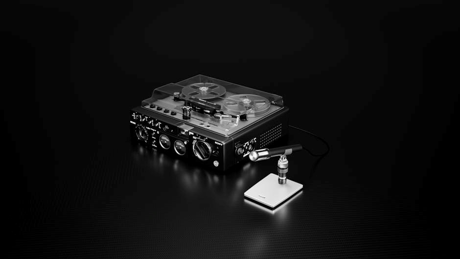
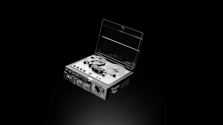
The Icom IC-706MKIIG is a highly versatile and compact multi-band transceiver, designed for both amateur radio enthusiasts and professionals. It covers the HF, VHF, and UHF bands, offering a wide range of operating capabilities in a relatively small package. This transceiver is renowned for its robust construction, reliable performance, and user-friendly interface.
As a service manual resource dated 04/16/2026, this guide aims to provide detailed information for technicians and experienced users undertaking repairs or advanced adjustments. It’s important to note that this manual focuses on the internal workings and maintenance procedures, complementing the standard operating instructions. Understanding the transceiver’s architecture and functionality is crucial for effective troubleshooting and service. This manual will help you maintain peak performance.
Key Features and Specifications
The Icom IC-706MKIIG boasts a wide frequency coverage, spanning 100 kHz – 1300 MHz, encompassing HF, VHF, and UHF bands. It delivers 100W output power on HF and 50W on VHF/UHF, offering substantial range. Key features include all-mode operation (SSB, CW, FM, AM), a built-in antenna tuner for simplified antenna matching, and a 32-bit floating-point DSP for enhanced signal processing.
Further specifications, relevant as of 04/16/2026, include a 3.7” LCD display, 100 memory channels, and support for digital modes like PSK31 and RTTY via an external interface. The transceiver also incorporates a VOX function and offers adjustable microphone gain. Its compact size and rugged design make it ideal for portable and mobile operation, ensuring reliable communication.

Getting Started
Begin your journey with the IC-706MKIIG by carefully following these initial steps, ensuring proper setup and operation for optimal performance as of 04/16/2026.
Unboxing and Initial Setup
Upon receiving your Icom IC-706MKIIG transceiver (as of 04/16/2026), carefully inspect the box for any signs of damage during shipping. Once confirmed, open the packaging and verify that all included components are present. These typically include the transceiver itself, a hand microphone, DC power cable, and this comprehensive operating manual.
Before proceeding, lay out all items on a clean, well-lit surface. Familiarize yourself with the transceiver’s front panel controls and rear panel connectors; A quick visual inspection will help you understand the layout. Ensure you have a suitable power supply capable of providing the required voltage and current. Finally, double-check the included accessories against the packing list to confirm everything is accounted for before initial power-up.
Powering the Transceiver

The Icom IC-706MKIIG transceiver requires a stable 13.8V DC power source (current date: 04/16/2026). Connecting to an inappropriate power supply can cause damage; Use the supplied DC power cable, ensuring correct polarity – center positive and sleeve negative. Before connecting, verify your power supply’s output voltage with a multimeter.
Plug the DC power cable firmly into the rear panel DC input jack. For mobile operation, connect to a regulated power supply in your vehicle. For stationary use, a suitable DC power supply is recommended. Avoid using batteries without a regulator. The transceiver will power on automatically when the DC cable is connected, displaying the startup screen. Always disconnect the power before making any connections or adjustments.
Antenna Connections
Proper antenna connection is crucial for optimal performance of your Icom IC-706MKIIG (current date: 04/16/2026). The transceiver features a single antenna connector on the rear panel, supporting HF, VHF, and UHF bands. Use a high-quality 50-ohm coaxial cable with appropriate connectors (typically PL-259 for HF and SMA for VHF/UHF).
Ensure the coaxial cable is in good condition, with no kinks or damage. Connect the coaxial cable securely to the antenna connector. A poorly connected antenna will result in reduced transmit power and poor reception. Always use an antenna matched to the desired frequency band. Consider using an antenna tuner for optimal SWR readings, especially on HF bands. Disconnect the power before connecting or disconnecting antennas.
Operating Modes & Functions
The IC-706MKIIG transceiver supports diverse modes, including HF, VHF, and UHF operation, offering versatility for various communication needs as of 04/16/2026.
HF Operation
The IC-706MKIIG excels in HF communication, offering a broad frequency range for worldwide contacts. Utilizing the transceiver on HF bands requires careful antenna selection and matching for optimal performance. Ensure a properly tuned antenna system to maximize signal strength and minimize SWR.
Explore various HF modes like SSB for voice communication, CW for Morse code, and digital modes such as PSK31 and RTTY. The built-in antenna tuner assists in achieving a good match, enhancing transmission efficiency. Remember to consider propagation conditions and band openings for successful long-distance communication.
Adjusting the RF power output is crucial; start with lower power levels and increase gradually to avoid interference. Familiarize yourself with the IC-706MKIIG’s HF filters to reduce noise and improve signal clarity. As of 04/16/2026, proper HF operation unlocks global communication possibilities.
VHF/UHF Operation
The IC-706MKIIG’s versatility extends to VHF and UHF bands, ideal for local communication and repeater access. Effective VHF/UHF operation relies heavily on antenna choice; shorter antennas are typical for these higher frequencies. Ensure your antenna is appropriate for the specific band you intend to use.
FM is the predominant mode for VHF/UHF voice communication, offering clear and reliable connections. Utilize the transceiver’s scanning function to monitor local repeater frequencies. Understanding offset frequencies and CTCSS/DCS tones is vital for accessing repeater systems.
Adjusting the squelch control effectively minimizes background noise. As of 04/16/2026, remember to adhere to local regulations and repeater etiquette. Proper VHF/UHF setup unlocks convenient and localized communication capabilities with the IC-706MKIIG.
SSB, CW, FM, and AM Modes
The IC-706MKIIG supports a wide range of operating modes, including Single Sideband (SSB), Continuous Wave (CW), Frequency Modulation (FM), and Amplitude Modulation (AM). SSB is favored for long-distance HF communication due to its efficiency. CW, or Morse code, offers a narrow bandwidth, useful in challenging conditions.
FM excels in local VHF/UHF communication, providing clear voice transmission. AM, while less common, can be used for broadcast listening and experimentation. Mode selection is straightforward via the front panel controls.
Proper microphone technique is crucial for SSB clarity. Adjusting the speech processor enhances signal strength. As of 04/16/2026, mastering these modes expands your operational capabilities. Experimentation is encouraged to find what best suits your needs and communication goals with this transceiver.
Digital Modes (PSK31, RTTY) ― Interface Requirements
Operating digital modes like PSK31 and RTTY with the IC-706MKIIG requires a suitable interface between the transceiver and your computer. A standard PC sound card interface, utilizing the radio’s rear panel DATA ports, is commonly used for PSK31. For RTTY, a dedicated interface box providing proper timing and signal conversion is often preferred.
Software such as FLDIGI or WSJT-X manages the encoding and decoding of these digital signals. Correct audio level adjustments are critical for optimal performance. As of 04/16/2026, ensure proper grounding to minimize noise and interference.
Careful configuration of both the radio and software is essential for successful digital communication. Experimentation with settings will yield the best results.

Menu Navigation & Settings
The IC-706MKIIG’s menu system allows extensive customization, enabling users to tailor the transceiver’s operation to their specific preferences as of 04/16/2026.
Understanding the Menu Structure
The IC-706MKIIG utilizes a multi-layered menu system, accessed via the ‘MENU’ key on the front panel. Navigation is achieved using the main encoder knob and the ‘A/B’ keys for selection. The menu is logically organized into several categories, including General, Display, Frequency, Antenna Tuner, and Digital Mode settings.
Each category contains numerous parameters that can be adjusted. Submenus are indicated by a flashing cursor, and changes are confirmed by pressing the ‘MENU’ key again. A hierarchical structure allows for efficient access to specific settings. Remember to consult the detailed menu map within this manual (dated 04/16/2026) for a complete overview of all available options and their functions. Understanding this structure is crucial for maximizing the transceiver’s capabilities.
Setting the Frequency
Frequency setting on the IC-706MKIIG is versatile, offering direct keypad entry, rotary encoder control, and memory channel recall. Direct frequency input is achieved by pressing the ‘FREQ’ key followed by numerical entry via the keypad. The encoder knob allows for incremental frequency adjustments, with the ‘A/B’ keys switching between coarse and fine tuning.
To select the desired band, use the ‘BAND’ key to cycle through available options. Ensure the correct mode (HF, VHF, or UHF) is selected before entering the frequency. Remember to consider regional regulations and licensing requirements when operating on different frequencies. As of 04/16/2026, always double-check your settings before transmitting to avoid interference or legal issues.
Adjusting Power Output
Power output adjustment on the IC-706MKIIG is crucial for efficient communication and legal compliance. The ‘PWR’ key cycles through available power levels: Low, Medium, High, and Full. The specific power output in Watts for each level varies depending on the selected band and mode.
Monitor the transceiver’s power meter while adjusting to ensure you’re operating within legal limits. Using excessive power can cause interference and potentially violate regulations. As of 04/16/2026, always verify your power output with an external power meter for accurate readings. Remember to consider antenna efficiency when determining appropriate power levels for optimal signal reach.

Setting the VOX Function
The IC-706MKIIG’s VOX (Voice Operated Exchange) function enables hands-free operation, automatically transmitting when voice input is detected. Access the VOX settings through the menu system; adjust the VOX level to suit your voice and ambient noise conditions. A higher level requires a louder voice, while a lower level is more sensitive.
Experiment with the VOX delay setting to prevent “keying slap” – unwanted transmissions caused by brief audio spikes. As of 04/16/2026, proper VOX setup minimizes background noise triggering transmission. Careful adjustment ensures reliable hands-free operation without accidental broadcasts.
Microphone Adjustment
Optimizing microphone settings is crucial for clear and intelligible transmissions with the IC-706MKIIG. Begin by adjusting the microphone gain to achieve a strong, yet undistorted, audio signal. Monitor your voice level using the transceiver’s meter; aim for peaks around the 70-80% mark.
Experiment with the microphone equalization settings, if available, to tailor the audio frequency response to your voice. As of 04/16/2026, proper microphone adjustment enhances communication quality. Ensure the microphone is positioned correctly and speak clearly for optimal performance. A well-adjusted microphone significantly improves your signal’s readability.

Troubleshooting Common Issues
This section details solutions for typical problems encountered with the IC-706MKIIG transceiver, as of today, 04/16/2026, ensuring reliable operation and quick fixes.
No Transmit Power
If you experience no transmit power with your IC-706MKIIG, begin by verifying the power supply connection and ensuring sufficient voltage is reaching the transceiver, as of 04/16/2026.
Next, check the transmit switch and microphone connection; a faulty microphone or improperly engaged switch can prevent transmission. Confirm the correct transmit mode is selected (SSB, FM, etc.).
Inspect the antenna connection for proper impedance matching and ensure the antenna is not damaged. A high SWR can trigger the transceiver’s protection circuit, inhibiting transmit power.
Review the menu settings related to power output and confirm it isn’t set to a minimum or disabled. Finally, if the issue persists, a potential internal fault may require professional servicing.
No Receive Signal
Encountering no receive signal on your IC-706MKIIG requires systematic troubleshooting, as of today, 04/16/2026. First, verify the antenna connection and ensure the antenna is properly connected and undamaged. Check the antenna cable for breaks or shorts.
Confirm the correct operating mode is selected (SSB, FM, etc.) and the squelch control isn’t set too high, blocking weak signals. Adjust the RF gain control to optimize sensitivity.
Inspect the band selector and ensure it’s set to the desired frequency range. A faulty antenna tuner or incorrect filter selection can also contribute to signal loss.
If the problem persists, consider a potential internal issue with the receiver circuitry, necessitating professional repair and diagnostics.
Display Problems
Addressing display issues on your IC-706MKIIG, as of today, 04/16/2026, begins with checking the brightness and contrast settings. Ensure they are appropriately adjusted for optimal visibility in your operating environment. A dim or flickering display often indicates a power supply issue or a failing backlight.
Verify the transceiver is receiving adequate power. Low voltage can cause display malfunctions. Inspect the internal fuse related to the display circuitry; a blown fuse will obviously cause a blank screen.
If the display shows garbled characters or segments are missing, it suggests a problem with the display driver IC or the LCD panel itself. This typically requires professional repair or component replacement.
Consider environmental factors like extreme temperatures, which can temporarily affect LCD performance.
SWR Issues and Antenna Matching
High SWR (Standing Wave Ratio) on the IC-706MKIIG, as of today, 04/16/2026, indicates a mismatch between the transceiver’s output impedance and the antenna system’s impedance. This can damage the final amplifier. Begin by verifying proper antenna connection and cable integrity.
Utilize the built-in SWR meter to assess the impedance match across the desired frequency range. A reading above 2:1 is generally considered high and requires attention. Ensure the antenna is resonant at the operating frequency.
Employ the transceiver’s internal antenna tuner to automatically adjust the impedance match. If the tuner cannot achieve a satisfactory SWR, investigate the antenna system for issues like incorrect length, damage, or nearby obstructions.
Proper antenna matching is crucial for efficient transmission and preventing transceiver damage.
Advanced Features & Techniques
Explore the IC-706MKIIG’s capabilities, including the built-in antenna tuner, filter optimization, memory programming, and CTCSS/DCS configuration as of 04/16/2026.
Using the Built-in Antenna Tuner
The IC-706MKIIG boasts a highly effective built-in antenna tuner, significantly enhancing transmission efficiency across a broad range of frequencies. This feature is invaluable for matching the transceiver’s output impedance to your antenna system, minimizing SWR and maximizing power transfer. To activate the tuner, access the menu and select the ‘Antenna Tuner’ function.
The transceiver will then automatically analyze the antenna system and adjust the internal matching network. A successful tune is indicated on the display. It’s crucial to ensure the antenna is connected before initiating the tuning process. The tuning process may take several seconds.
Important considerations: While the tuner handles many antenna impedances, extremely mismatched antennas may still present challenges. Regularly check SWR after tuning, especially when changing bands or frequencies. As of 04/16/2026, proper antenna tuning is vital for optimal performance and preventing damage to the transceiver.
Filter Selection and Optimization
The IC-706MKIIG offers selectable filters to optimize receive performance based on operating conditions. These filters help reduce interference and improve signal clarity. Access the filter settings through the transceiver’s menu system. Options typically include wider filters for general scanning and narrower filters for weak signal work or crowded bands.
Choosing the right filter is crucial: Wider filters provide a broader bandwidth, capturing more of the signal but also more noise. Narrower filters reject more off-frequency interference, enhancing weak signal reception. Experiment with different filter settings to determine what works best for your specific situation.
As of 04/16/2026, remember that filter selection is a dynamic process. Adjust filters as band conditions change to maintain optimal receive quality and minimize unwanted signals. Proper filter optimization significantly improves the user experience.
Memory Channel Programming
The IC-706MKIIG’s memory channel system allows you to store frequently used frequencies for quick recall. Access the memory mode via the transceiver’s front panel. To store a frequency, tune to the desired signal, then press the ‘MEM’ button followed by a memory channel number (01-99). Confirm the storage process.
Recalling a memory channel is equally simple: press ‘MEM’ followed by the channel number. The transceiver will instantly tune to the stored frequency. Memory channels can be overwritten or cleared as needed. Utilize the memory scan function to cycle through stored frequencies automatically.
As of 04/16/2026, effective memory management is key to efficient operation. Organize frequencies by band or purpose for easy access. Regularly review and update your memory channels to reflect your current operating needs.
CTCSS/DCS Configuration
The IC-706MKIIG supports both CTCSS (Continuous Tone-Coded Squelch System) and DCS (Digital Code Squelch) for enhanced privacy and selective calling. Access the CTCSS/DCS settings through the transceiver’s menu system. Select either CTCSS or DCS mode, then choose the desired tone frequency or code.
Proper configuration is crucial for successful communication on repeater systems. Ensure your transceiver’s CTCSS/DCS settings match the repeater’s requirements. Incorrect settings will result in no audio reception. The transceiver allows you to set separate CTCSS/DCS tones for transmit and receive.
As of 04/16/2026, verify settings before transmitting. Refer to repeater directories for correct tone/code information. Experiment with different settings to optimize performance and minimize interference.

Service Manual Overview (Based on Available Information ― 04/16/2026)
This service manual, current as of today, 04/16/2026, details the IC-706MKIIG’s internal workings, including block diagrams, alignment, and component replacement procedures.
Block Diagram Explanation
The IC-706MKIIG’s block diagram illustrates the transceiver’s functional sections, revealing signal flow from antenna input to final RF amplification and vice versa. Key blocks include the receiver front-end, mixer, IF amplifier, demodulator, and audio amplifier stages. The transmitter section features a VOX circuit, microphone amplifier, modulator, RF amplifier, and antenna output.
Understanding these interconnected blocks is crucial for troubleshooting. The diagram highlights the path of signals, enabling technicians to isolate faults within specific stages. For example, a lack of signal after the mixer suggests issues with the local oscillator or front-end components. Conversely, a weak transmitted signal points to problems in the RF amplifier or power supply.
Detailed annotations on the diagram identify critical components and test points. This allows for precise measurements and verification of signal levels throughout the transceiver. Careful study of the block diagram, combined with the alignment procedures, forms the foundation for effective IC-706MKIIG service and repair.
Alignment Procedures
Proper alignment is essential for optimal IC-706MKIIG performance. These procedures, detailed within the service manual, ensure accurate frequency calibration, sensitivity, and transmit power. Alignment requires specialized equipment, including a signal generator, frequency counter, and RF power meter. Caution: Incorrect alignment can degrade performance or damage the transceiver.
Initial steps involve verifying the local oscillator frequency and adjusting the variable capacitors for precise calibration across all bands. Receiver sensitivity is then optimized by adjusting the RF and IF amplifier stages for maximum signal strength. Transmitter alignment focuses on setting the carrier frequency, modulating the signal, and achieving the specified power output.
Detailed instructions and test point locations are provided for each alignment procedure. Technicians must carefully follow these steps, monitoring signal levels and frequencies at each stage. Regular alignment, as part of preventative maintenance, maintains the IC-706MKIIG’s reliability and performance.
Component Replacement Guidelines
Replacing components in the IC-706MKIIG requires careful attention to detail. Always use components with identical specifications or approved Icom replacements to maintain performance and reliability. Prior to any replacement, ensure the transceiver is disconnected from the power source to prevent electrical shock and damage. Static discharge precautions are also crucial, utilizing a grounded wrist strap.
Soldering and desoldering should be performed with appropriate tools and techniques, avoiding excessive heat that could harm surrounding components. Pay close attention to polarity when replacing electrolytic capacitors and diodes. After replacement, thoroughly inspect the solder joints for cold solder or shorts.
The service manual provides detailed schematics and component layouts to aid in identification and placement. Document all replacements for future reference and maintain a clean, organized workspace. Proper component replacement ensures the longevity and optimal operation of your IC-706MKIIG transceiver.
Comments